Level shifting is absolutely a thing, and it’s more challenging than it appears on first glance. You have to worry more about dynamic response than you’d think. The TXS0108E mentioned above is a solid choice for many uses, but you still have to be cautious, in particular cautious about long traces.
My PCB has five LVC245s (multivoltage tolerant transceivers) powered at 3.3V, and one TXS0108E, dual powered at 3.3V and 5V, to cover the various needs for interfacing the Apple II bus. The transceivers handle the bidirectional bus and the input-only signals, while the TXS0108E is for handling the shared wired-OR signal lines, where there’s a pullup resistor on the line, but any of the cards on the bus can choose to signal by pulling the line low. The classic way to do that is with an open collector buffer, but the TXS0108E does a good job, where you set the pin to input (high impedance) when you don’t want to signal the line, but turn the pin to output-0 to pull it low. And when the line is set input, you can also read the pin to see when something else might be asserting the line!
Hi,
What is purpose of RN1 100OHm resistor net, please? The FLASH signals are not connected to any socket so that it can’t be programmed externally.
Thanks a lot
Lots of questions to unpack. Let me know if I miss any.
The new boards use different inductors. The old inductors are too tall (new boards are only 4mm apart instead of 6mm). The new inductors are blocks instead of the )( shape of the old ones. I have two boards on my desk with cracked inductors (they seem to work fine) so I’m well aware this was an issue (especially with how SparkFun liked to ship them…)
You could extend the JTAG chain through the headers if you’re using an external JTAG interface but you can’t extend the chain seen by the FT2232.
Level shifting is often best tackled on a per-need basis. The requirements vary wildly and stuff like bi-directional shifters are often not great as they necessarily have weak drive strengths (so either side can overpower them). This means any board we made would have dedicated inputs and outputs limiting its use.
I learned this the hard way with the Servo Shield for the Mojo which used MAX3002 shifters. Some servos had low enough input resistances to make the chip think it was driving its side low. The measured voltage on the signals ended up closer to 3.3V instead of 5V. Some servos were cool with that, others not so much. Either way the chip was useless for this and just feeding 3.3V to the servos would’ve been better. On the other hand, they work great for I2C but you can often get away with a basic transistor version.
As @Jflanagan pointed out, they needed to use different ICs for different needs.
RN1 is just there to help protect the FPGA/FLASH IO if you make a mistake and attempt to drive a pin being driven by the FLASH as the data lines are all bi-directional.
The point about bidirectional shifting is quite pertinent- I use the lvc245 transceivers for the bidirectional bus because, unlike the txe0108e, they are full-powered outputs. Although I’m cheating a bit, they are powered at 3.3V, and thus are only putting 3.3V out on the 5V side. Fortunately that’s plenty high enough to count as “high” on the 5V bus in question. If I was having to convert from 1.8V, for instance, I’d be having to use a full dual-voltage transceiver instead.
The disadvantage of those transceivers is that their direction control is all or nothing- all 8 data lines have to be going the same way. This is not a problem for the address lines or data lines of course, they are always going the same way!
The txs0108e is having to solve the different problem where I need to be able to assert any of the eight lines independently, in any combination. The low drive strength is not a disadvantage because I’m only using it to drive low, and it’s plenty capable of sinking the line fast enough. And when I stop asserting it low (going high impedance input on my pin) it pulls itself up fast enough to also be fine.
But the 0108 failed me in another situation where I was trying to breadboard a different system, and my wires were long enough that I was getting reflections. However it also saved me from blowing anything up when I initially wired everything wrong, because its weak drive strength meant it didn’t damage anything on the $1000 dev board when it was misconfigured to drive into the face of output pins on the dev board. So there’s that.
The Au prototypes arrived today! They looks pretty great. I haven’t had a chance to do much testing but the power supply checks out (expected voltages were there). I’ll do more testing tomorrow.
How about a jumper or a switch that would allow to open the chain so the existing pins on the headers can be used to extend it?
I have JLink but the ability to extend the chain saw by the FT2232 would save some wiring and the use of an external probe
Also, a small detail which I do not think should be too hard to add, an on LED. It is a bit confusing that you have a done LED but no on LED, and gave me a bit of a scare when I first tried the Alchitry Au before I realized the LED only lights up when programed.
Adding a way to break the JTAG chain would add a fair amount of extra complexity for something I think very very few people would ever use.
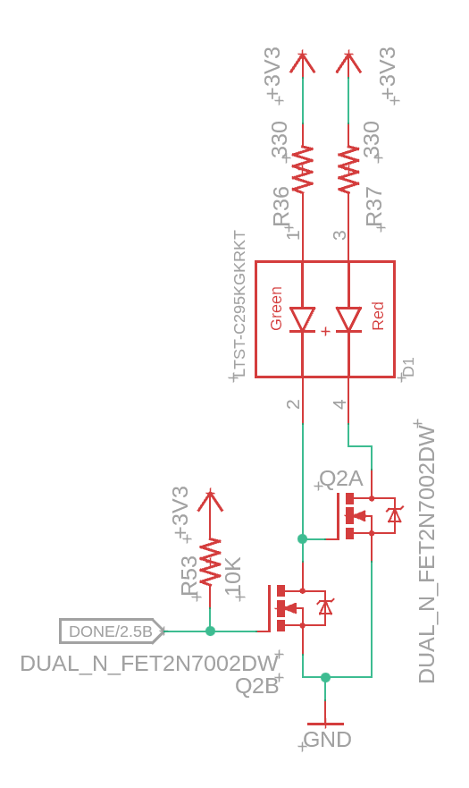
I didn’t want to clutter the board with LEDs that just sat there. However, I too don’t like that you have no indication of power if the FPGA isn’t programmed. To keep things simple/pretty, I redesigned the DONE LED to use a dual color LED. It’ll now be red when the board has power but the FPGA isn’t configured and green when configured.
Nice!
I wonder how the built-in thermal protection work regarding to the device’s temp range.
I mean is it the same fixed temp for every variant or did they set a temp according to the device’s range?
I didn’t found the related doc so far.
I believe it’s triggered off the over temp flag from the XADC but I couldn’t find anything about what threshold that is. I did find a mention of someone saying they set it to 75C so I don’t know if this is configurable somewhere. I’ll have to dig more.
This was changed to allow for a little more flexibility in IO standards that can be used.
The big push for me was this enables using the triple voltage pins as MIPI D-PHY outputs (see page 16). MIPI is the standard used by many embedded cameras and displays. The Raspberry Pi uses this for its cameras and display output.
In theory this would let you design something where the FPGA provides a camera feed to a Raspberry Pi.
Cool!
I have a Pi cam I use to watch out my 3D printer, I could play around with it
And the added flexibility makes the boards more attractive
Would it be possible to have a MIPI input and a MIPI output at the same time so we could fiddles with a live video feed in-beetween?
Is there enough tri-voltage pins available?
The solution for MIPI inputs can actually be on any pins as long as VREF can be set to 0.6V for the HSUL_12 pins. This just means they can’t be on a bank as other pins that require a different VREF (most don’t).
Be nice if you made a board based on Zynq or something that is half ARM / half FPGA. There is ZTurn but they don’t update the BSP so uses old tools. Be nice to have something using the latest tools with lots of IO pins.
A Zynq board is something that’s been on my radar for a long time. It’s probably likely to be the next main board I design but that’ll be some time as I work on the rollout of all the V2 stuff.
I’m planning to make a PCIe adapter for the Pt that hooks up to the new Raspberry Pi which could fill a similar role.