I spent a good amount of time today trying to get the Ft v2 board working with the Pt FPGA board. I had put the FPGA board on top and the Ft board under it. I could talk to it via the FTDI drivers and C code, but it was timing out trying to do a loop-back. (I tried it with a Fn fan board in-between and without, although I realize a capacitor hits the USB connector so I shouldn’t do that… I had forgot about reading that.)
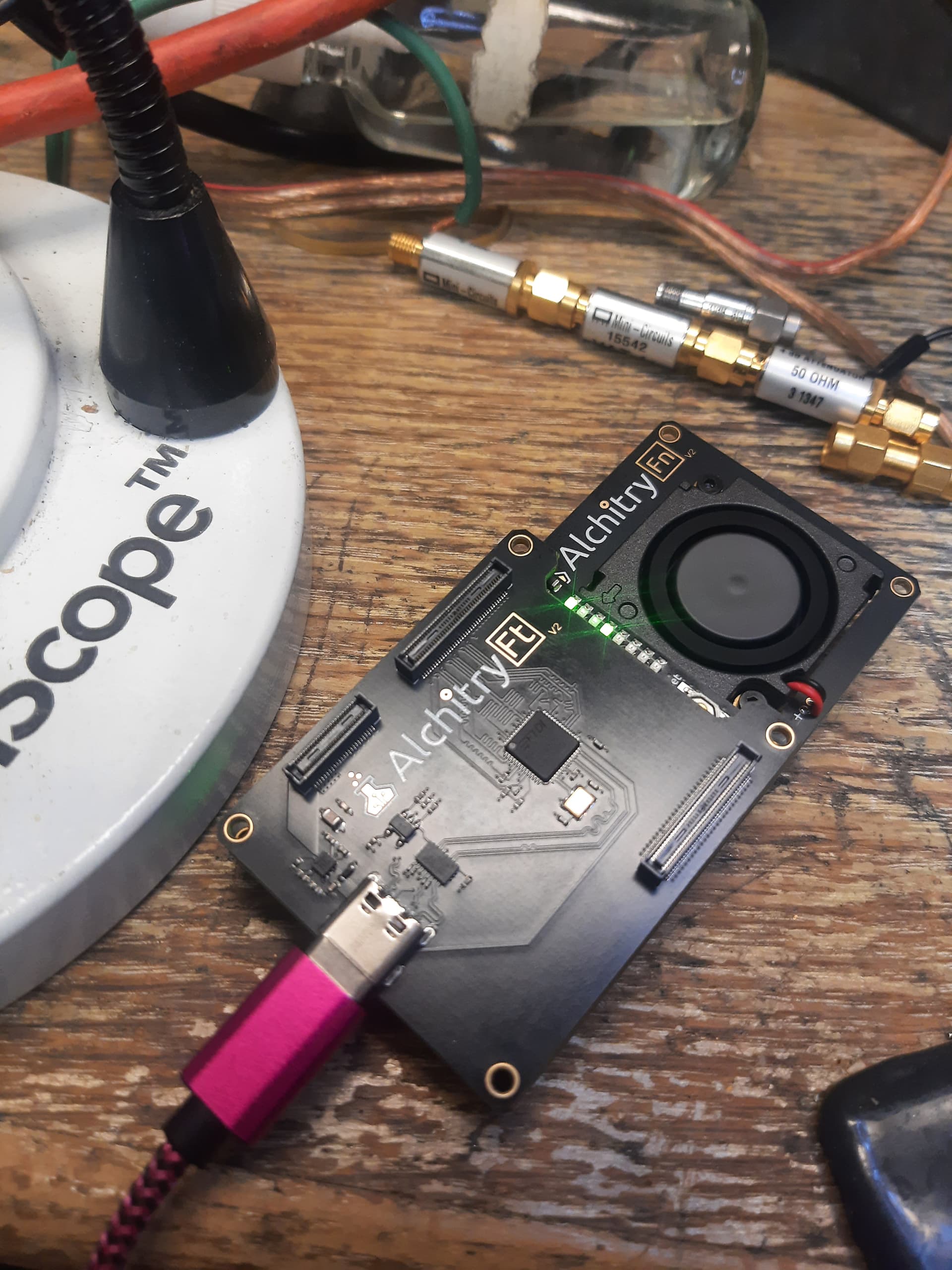
I moved it to the top side to probe it with a scope and suddenly it started working.
So is there a reason it won’t work correctly when mounted at the bottom? I thought the connectors were all the same on top and bottom. Am I missing something?
So far I’m pretty happy with these boards.
Photo attached with the working configuration of the board:
So is there a reason it won’t work correctly when mounted at the bottom? I thought the connectors were all the same on top and bottom. Am I missing something?
The top and bottom sides of the Pt are independent banks, you need to change your pins constraints to use the bottom side
As @gc74 said, the bottom and top are independent on the Pt with the top being the default.
See Alchitry Constraints Reference for how to easily switch to the bottom (you need a spacer). The pinouts aren’t exactly the same and some boards may not work on both sides due to the GTP pins. None of our boards are like that yet though.
Thanks a ton! That explains it. I didn’t realize the pins were not all identical pass through copies on top and bottom.
You could apply the old joke about what happens when we ‘ass’ume something like that.
On the other hand having it able to seemingly plug in two ways but only have one that works is a direct and literal violation of Murphys law. So it should have a large call-out at least in the comments of the tutorial code. Possibly also right on the product page. Did I miss some background reading that “everyone” knows about?
I’m sure you have way more work than time… but here is my feedback as a new user. It would be nice to have a brief hardware setup guide in the tutorial section (as a new customer that’s where I looked) that could explain the Ft hardware setup and gotchas all in one place. It could explain how to find the Ft demo project in the tool. It could mention that the Ft must be on top for that project, the physical conflicts on the bottom, pinout changes needed etc. It could mention that the bandwidth might be limited if you use a USB 2 cable on accident… all the stuff I did wrong on the first try. etc.
What software can I run to confirm the Ft demo is working? I used the ftdi example c code.
Even “obvious questions” like Is it okay to power with both Pt and Ft usb cables. Etc.
How to get the boards apart without flinging them across the room.
Thanks for a very cool product. I’m currently looping data from pc to fpga and back to disk at 6.7MB per second with no loss. I will try again when I get a proper usb 3 cable. The one I have has a blue colored inside on the A side but isn’t actually usb 3 compliant, having only 4 pins in there. Shameful to do that, but I guess it sells more units. Ha.
The Pt is the first Alchitry board which has different top and bottom pinouts. Had you made that assumption with any other board, you would have been correct! The previous boards work in the fashion you were expecting. The reason this was done on the Pt is that it uses a larger chip footprint with vastly more GPIO. There’s (approximately) twice as many pins available. I expect that splitting the top and bottom connectors into being separate sets of GPIO was the most feasible option for getting more GPIOs off of the board. Figuring out the alternate constraints to route to the top or bottom connector is a hurdle, but a relatively small one.
Hah, I screwed up the USB3 cable thing too! I got everything working, and was like, “Why is the bandwidth so low? Why is the low bandwidth suspiciously close to the max USB2 bandwidth?” (narrows eyes)
The knowledge that the top and bottom connectors are different on the Pt was covered extensively in the forum thread where the new v2 boards were announced and discussed. Which is more or less that “background reading” you theorized. I have to agree that it could be better documented
Well at least the next person will be able to find this discussion in the forums!
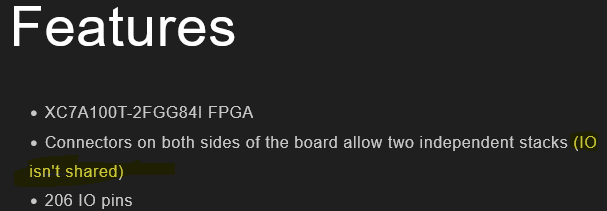
I knew the top and bottom of the Pt were different, and I did see the mention saying “IO isn’t shared”. I knew this explicitly was important because I intend to try to use the GT transceivers on this board.
However, I’m serious about considering how Murphy’s law applies to good design practices. Murphy’s law was originally about wiring harnesses (an exact analogy here) and that if you could connect them wrong somebody would. This is exactly what I did.
Not only that, it is hardly noticeable that the capacitor hits the USB-C when hooked up with Ft on the bottom. I’m glad that I didn’t short something out and damage something when I fired it up that way. It’s not such a complete collision that the boards don’t mate. They had seemed to click together fine. If you re-spin it seems like you could avoid this collision. (Or maybe better to double-down and put a giant through hole part in a safe spot to completely prevent mating on the “wrong’“ side. Ha! Although you could still screw it up with a spacer board in-between.)
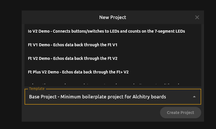
I’m not an idiot… usually… however, I am completely new to the Alchitry designs and I have not read every word of every forum thread (yet). Another feedback/suggestion (minor of course) is that now that the Pt has two different pin-outs top and bottom, you could either have two different clearly marked templates for the Ft when you select the “Alchitry Pt V2” board: instead of just Ft V2 Demo it should be “Ft V2 Demo, Ft on Top of Pt” and “Ft V2 Demo, Ft on Bottom of Pt”…
Or if you don’t want to have both options, at least rename the one that is there “Ft V2 Demo, Ft on Top of Pt.”
Discovered that my fancy USB C cable is only 480MBps. It says right in the description. Ugh. But also: that’s great!
I grabbed a different cable, confirmed the number of pins visually (USB-A to USB-C, 9 pins.)
It immediately shows up as USB3:
/: Bus 002.Port 001: Dev 001, Class=root_hub, Driver=xhci_hcd/10p, 5000M
|__ Port 007: Dev 002, If 0, Class=Vendor Specific Class, Driver=usbfs, 5000M
|__ Port 007: Dev 002, If 1, Class=Vendor Specific Class, Driver=usbfs, 5000M
Kinda bad news though:
It’s only pushing about 8MB/sec which is about 24 times slower than expected.
Dumb thing to try: try unplugging the USB-C side of the cable, flipping it over, and plugging it back in. This has a low probability of working but try it anyway.
There’s a circuit on the Ft board which detects the orientation of the plug and flips it if needed, to align the pins to what the FT601 expects. It’s possible that something is going wrong with that circuit, plugging the cable in the other way is an easy way to eliminate it.
The reason I know about this is because in my own project, we did our own FPGA board including an FT601 chip, and the hardware guy included the flip circuit and got it backward, so that it was always in the wrong orientation regardless of how you plugged it in.
See if this helps, I doubt that it will but it is an interesting thing to share knowledge about.
Oh, actually, another thing I just remembered about! Modify the Alchitry image to use much bigger buffers! I forget what the default size of buffers it creates for the FT600 driver, but they aren’t big enough. Make them like 8x bigger.
Specifically, set the RX_BUFFER and TX_BUFFER parameters in the ft.luc file to be something like 512 or 1024 instead of just 64. Because these buffers are so small, they aren’t able to completely fill the maximum 1024-byte USB bulk packet size. You want to not only be big enough to fill the packet size, you also want to be big enough to have extra buffer space for starting another packet.
And another thing I note is that you’ve got an Ft instead of an Ft+. That’s going to be another doubling of the buffer size you want to use, because the Ft operates on 16 bits at a time instead of 32, so you need twice as many buffer entries to properly receive or send a full 1024 byte USB bulk packet. If increasing the buffer size improves your throughput, keep increasing it until it no longer does
Thanks for these notes. I was aware of the pin swap circuit on the schematic. There isn’t much else on that schematic. I also knew of the flip the cable risk/trick.
But now that I have a good cable it enumerates fine at 5000Mbps. But the bandwidth is stuck just under 12MB/sec no matter what I do with asynch or synch reads or writes or overlapped or not or buffer size.
I’m worried that this may be a problem with the Linux driver or code. I don’t see that anyone has published Linux bandwidth numbers.
I’m going to build an image to just test write bandwidth next by setting OE and RD always active.
I’ll also fix the buffer sizes in the hdl project. That is a very important thing I had not considered and was not aware of.
Oh, the driver issue might be pertinent. I don’t ever remember trying with just vanilla drivers, I always downloaded the FT3xx sdk and used their driver. That’s very likely to be an issue for you as well.
It is absolutely possible to get very nearly the full theoretical bandwidth once you sort out all the little details, I’ve done it. I haven’t gotten my project up to the point of needing that bandwidth yet, and I am working on migrating over to a Zynq 7020 based system so I probably won’t wind up doing it with Alchitry unless this other effort winds up not panning out for some reason.
Depending on how things go with that project, I might just be satisfied with USB2 rates, or GigE rates (the zynq ARM cores natively support both of those if you connect the appropriate PHY hardware). We probably will have enough pins on the FPGA side to connect an FT601 if we ultimately desire more than GigE bandwidth, and/or want high bandwidth without having to deal with networking config. For something that wants to just be plug-and-play, USB is much easier to deal with.
I am using the ft3xx linux drivers downloaded from ftdi. I don’t know what a “vanilla” driver would even be in this case, since the part is completely proprietary.
I’m concerned though that the linux drivers might not be up to snuff. The FTDI website lists windows as “recommended” with no rationale. Maybe the linux drivers I’m using from this page are “toy” drivers that don’t actually implement proper buffering? Probably, that’s not the issue, but I just don’t know what I don’t know.
In my case, I’m migrating away from a Zynq system. Ha! That approach didn’t pan out for me.
I don’t see any timing constraints besides the 100MHz clock constraints in the ft_v2.acf and alchitry.acf files. Am I missing something, or are those really the only constraints needed?
I ask, because I can’t determine the trace delays on the board myself, I haven’t noticed them published anywhere, and I’m used to seeing a small handful of other constraints for a 16 bit interface at 100 MHz.
The link below shows roughly what I would expect for the constraints.
I haven’t done it on a full desktop or server Linux system, but on an RPi5, I was able to get something like 70-80% of max throughput, far above what you’re seeing. And I suspected the limitation there was the Pi hardware rather than the Linux running it.
I don’t think you need to be worrying about trace delays. I recall asking on the forum somewhere about the possibility of doing the FT601 routing on my own board so I would be able to have a shorter stack (just Au v2 and my board, instead of Au v2, Ft+ v2, and my board), and the feedback I got was something like “the timings on the ft601 are pretty generous, just make some kind of attempt to keep the traces reasonably matched and it’ll be fine”, so I don’t think it needs super close review.
The ft_v2.acf and alchitry.acf files are indeed the only constraints needed at the Lucid level. You can dive into the generated Vivado output to see the entire nuts-and-bolts detail if you like. Everything Alch Labs does is just preprocessing and then creating a regular Vivado build directory, and gives you an eaiser framework to work with rather than forcing you to smack your head directly on the steep Vivado learning curve. Once I found my feet, I did all of my development directly in Vivado, only using Alch Labs to spit out the basic framework which I transcribed to my own project and started working on it directly from there.
I am sufficiently novice at this stuff to not really know if part of the (many) warnings I would routinely get in Vivado were due to not having the kind of proper, formal trace length specifications you’re asking about. I did some pretty crude stuff to try to shut it up, out of impatience and ignorance, but maybe the correct approach should have been to model up all of the expected timings so that the tool would know about them.
Out of curiosity, what problems did you encounter with the Zynq approach?
edit: That’s a great article on the timings of the FT60x btw, thanks for linking it!
The bandwidth numbers on the product page were taken from Linux using D3xx. I used a slightly modified version of the streamer program FTDI provides that also checked for a data pattern to ensure integrity.
I used the Ft Plus demo project as is (buffers of 256) and this as my write-read loop.
static void stream_in(FT_HANDLE handle) {
    unique_ptr < uint8_t[] > buf(new uint8_t[BUFFER_LEN]);
    uint32_t next = 0;
    uint64_t total = 0;
    bool show_speed = true;

    auto start = std::chrono::high_resolution_clock::now();
    auto last = start;
    while (!do_exit) {
        ULONG count = 0;
        uint32_t *data = (uint32_t*) buf.get();
        for (size_t i = 0; i < BUFFER_LEN/4; i++) {
            data[i] = next + i;
        }
        FT_STATUS status = FT_WritePipeEx(handle, 0, (uint8_t *) data, BUFFER_LEN, &count, 1000);
        if (status != FT_OK) {
            cerr << "FAILED WRITE: " << status << endl;
            break;
        }
        if (count != BUFFER_LEN) {
            cerr << "Failed to write everything! " << count << endl;
            break;
        }
        status = FT_ReadPipeEx(handle, 0, buf.get(), BUFFER_LEN,
                               &count, 1000);
        if (status != FT_OK) {
            cerr << "FAILED READ: " << status << endl;
            break;
        }
        if (count != BUFFER_LEN) {
            cerr << "Failed to read, count: " << count << endl;
            break;
        }
        auto end = std::chrono::high_resolution_clock::now();
        auto duration = std::chrono::duration_cast<std::chrono::milliseconds>(end - start).count();
        total += count;
        if (std::chrono::duration_cast<std::chrono::milliseconds>(end - last).count() > 5000 && show_speed) {
            cout << "MBPS: " << total * 2 / duration * 1000 / 1000000 << "\n";
            last = end;
            show_speed = false;
        }

        if (count % 4 != 0) {
            cerr << "COUNT WAS NOT A BATCH OF 4!\n";
        }

        auto word_count = count / 4;
        auto word_buf = (uint32_t *) buf.get();

        for (size_t i = 0; i < word_count; i++) {
            //cout << (int)buf[i] << "\n";
            if (next != word_buf[i]) {
                cerr << "Word value mismatch at " << i << "! Got " << word_buf[i]
                     << " expected " << next << "\n";
            }
            if (next == 0xFFFFFFFF) {
                cout << "Fully tested!\n";
                cout << "MBPS: " << total * 2 / duration * 1000 / 1000000 << "\n";
            }
            next = word_buf[i] + 1;
        }
//        if (fwrite((const char *) buf.get(), sizeof(char), count, stdout) != count) {
//            cerr << "Failed to write full buffer size!" << endl;
//            do_exit = true;
//            break;
//        }
    }
}
There’s some loss for the back and forth but I’m seeing 284 MBps (bytes) on my desktop.
Sweet. I’m targeting a RPi5 compute module in the end anyway. Ha. So I won’t worry about it on my main PC then. I’ll head straight to the CM5. 70% of max should be enough for what I need. It’s great to have confirmation that it’s not a linux driver thing per se.
I spend my day job doing FPGA designs including the board level timing constraints for products that ship in very high volume and to very high visibility clients. (I work for Shure on their wireless stuff.)
My main concern is that I know how to analyze and enter the constraints if I need them, and that I haven’t missed constraints coming from places that I don’t know about. It seems everything ends up in .xdc files in the end, so I can just start from that.
I too will be using vivado directly. The lucid stuff and alchitry gui are cool, but I’m already an expert on verilog and vivado, so I might not spend much time working in lucid.
I’m an expert on vivado, and still the warnings terrify me. There is so much noise I worry about missing the signal.
I was trying to get unnecessarily fancy in the Zynq. I was using a snickerdoodle black because I had it on hand and it was pretty small. But it is really a better fit to use a board with proper transceivers. I had been working on an asynchronous deserializer. It was kinda working, but was causing signal integrity and timing problems. It was a bit of a ‘science fair experiment’ and without a real requirement to do it that way I couldn’t justify the time and risk involved.
I also dislike Zynq for ‘philosophical’ reasons, but I was willing to let that go.
Also it seemed silly for me to be doing linux on a zynq when a raspberry pi or a regular pc could be used for my use case. I prefer working with more commodity solutions… they have more support and are better tested and I have the option to escape if I decide to move to efinex or some other competitor in the future.
Ah, I see… I was trying to base my test on the async-loopback.c code. I had picked it due to it being c rather than c++ which was pretty arbitrary.
I just tried your code by splicing it into the streamer.cpp from ftdi. I’m not sure I did it right because it just hangs at the FT_WritePipeEx(). Any chance you could send me your complete modified version of streamer.cpp?
I also tried the default streamer.cpp code and I get similar speed numbers, capped at about 12 MiB/s