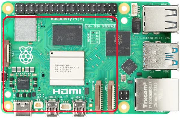
I’m starting to work on the Raspberry Pi PCIe adapter for the Pt and wanted to get some feedback on the form factor people would like to see.
My initial thought is to make it large enough to be bolted to the Pi like a standard “hat” with a cutout to keep the Pi’s 0.1” pins exposed. The downside with this is that the board wouldn’t be very stackable making the Alchitry pins hard to access. I guess the standoffs used to attach it to the Pi could be extra tall but that might require different ribbon cables for the PCIe connection.
It could also be designed to just be the same footprint as the Pt and sit beside the Pi. The extra IO on the Pt could then easily run to bottom side connectors. The ribbon cable could run out the right side to connect to the left side of the Pi.
Having it stackable on the Pi could be nice, and I saw some hats having a simple passthrough connector for the Pi expansion port (0.1’’), allowing to cleanly access to the pins to stack another hat on top or connecting a ribbon cable and also tapping the power pins for the hat if needed.
We could even route some of these to the FPGA maybe? I don’t know if this would be useful since we would have the PCIe already? Maybe for some control signals or JTAG so we could avoid the USB cable?
This would requires that the PCIe adapter to always be at the bottom of the Alchitry stack, but it sounds acceptable for me
I think if it is made to stack on the Pi, the most reasonable solution is to just have a cutout to not block the header.
Maybe we design it to sit on the side but offer an adapter to mount it on top? Like a 3D printed plate that you could buy or print yourself?
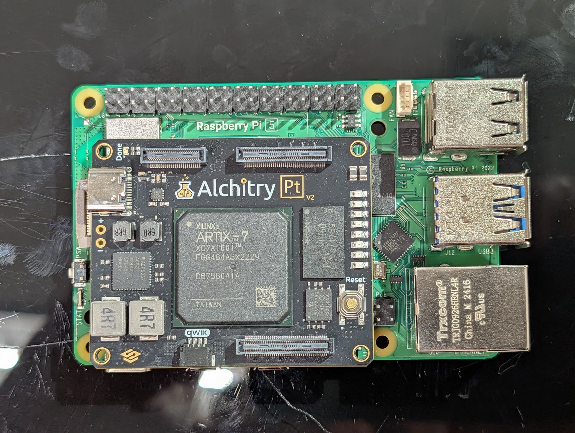
The PCIe adapter will always have to be right underneath the Pt because of the data rates. It also will need to use the 1.5mm stack height headers instead of the normal 4mm ones. Normal speed boards can stack underneath it though if we pass signals through.
You’d have to raise the board up decently to get a CSI/DSI cable out even with a cutout in an adapter but I don’t think that’s a big price to pay. You’d just need taller standoffs.
Yes, that’s what I had in mind, but I was wondering in which orientation to put the Pt, maybe rotating it 180° so the USB C port is facing the Pi’s USBs so it’s easier to plug the Pt or Ft to the Pi?
But then the USB cable could get in the way of the DSI/CSI ribbons so I’m not sure…
Angled USB cable would help.
Rotating the board 180 would then make it awkward to plug in when it is off to the left (not stacked). I think it is generally better for the port to be on the edge. If you moved it all the way right then you’d be off the mounting holes by quite a bit.
That connector is a clever way to avoid having to solder the long thru hole pins but if we aren’t using signals from the connectors (like the M.2 board does) then it is functionally the same as just a hole. You can use one of the long pinned connectors as an extension if needed without the passthru style connector on the board.
I think we start with the simple same-sized adapter intended to sit off to the left of the Pi with an adapter to mount it on top if needed. If there is enough interest, we could make a proper “Hat+” version that connects to the Pi’s power as well.
Sounds good to me, I could try playing around with my 3D printer in a few days, I have to fix first, thanksfully it’s a reprap one so I can use it to print it’s own parts, using a temporary workaround to make it usable enough to print the replacement.