Hey, I have been trying to find the part number of the LEDs on the board, for a different project i am working on. The schematics of the boards just say “LED#”, but no part numbers. Is there any source for part numbers of components on the board? If not, can somebody share the LED part number with me?
Honestly, they’re just generic LEDs. When we were manufacturing them we used LG R971-KN-1 but I can’t say for sure that’s the exact one SparkFun is using.
Hi
I’m looking for the part number of components used on Alchitry Au board.
From schematics I do get details that it is but for some components the part numbers are partial, Please advise.
What parts are you looking for? All the basic stuff (resistor, capacitor, etc) are generic and change run to run. The major components all have PN I believe.
For example, the connectors part number looks different on the schematic vs the Drawing pdf in the portal. DF40C-50DS-0.4V4.0 v/s DF40HC(4.0)-50DS-0.4V(51) which of these is actually used. Similarly even for the 80 pin connector need the PN.
Is there Bill of Material for this board that can be referred to? Please advise.
Board - Alchitry Au
Schematic - https://cdn.alchitry.com/docs/Au-V2/AuSchematic.pdf , Drawing https://cdn.alchitry.com/docs/Au-V2/AuDrawing.pdf
Sorry about the slow reply, I wanted to verify my PCB’s functionality completely enough to be sure that I had actually done it all right. Part of your confusion is that there are 4 connector parts in total:
DF40C-50DS-0.4V4.0 mates with DF40HC(4.0)-50DS-0.4V(51), they are separate but matching parts.
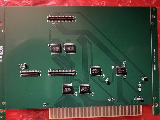
If you’re doing a board which is intended just to be the end of the stack (i.e. you aren’t going to put the mating connectors on the far side of your board to continue a stack), then you just need the DF40HC parts. Here are the LCSC numbers for the HC parts, if it helps you at all:
50 pin: C424645
80 pin: C294544
I only used this side of the connectors so I haven’t looked up the part numbers for their mating connectors.
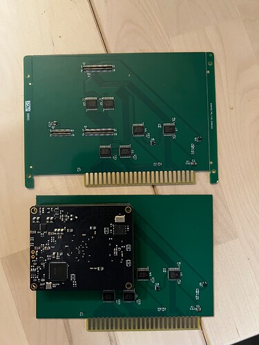
Here you can see my board, it mates perfectly and is functional in a stack with an Au v2 and an Ft+ v2.
Thank you for sharing details. So DF40C-50DS-0.4V4.0 and DF40HC(4.0)-50DS-0.4V(51) are matching/similar parts. The mating connector would be 50 pin: DF40C-50DP-0.4V(51) and 80 pin: DF40C-80DP-0.4V(58) right?
The connectors on the top of the board (ones on the Au/Cu) are DF40HC(4.0)-50DS-0.4V(51) and DF40HC(4.0)-80DS-0.4V(51). The (4.0) portion of the part number indicates the 4mm stack height. There are versions that are shorter if you don’t need the height. The 1.5mm stack height version can handle the speeds needed for the GTP pins on the bottom of the Pt.
These mate with the DF40C-50DP-0.4V(51) and DF40C-80DP-0.4V(51). These are found of the bottom of all elements and the bottom of the Pt.
See the DF40 catelog for more details.
Are these MPN used in Au the same as those in Cu?
also, any PCB template (Altium Designer) or a document providing precise position/location of the three B to B connectors?
The same connectors are used on all the boards. Future high speed boards like PCIe for the Pt will need to use the shorter versions.
See https://cdn.alchitry.com/docs/Au-V2/AuDrawing.pdf for connector placements.
I had no problem laying out my own kicad design using the measurements provided in that AuDrawing.pdf file.
Out of curiosity, are you powering the Au with a seperate USB-C cable or are you able to feed 3.3V power through the connectors?
In previous board iterations, I had a diode on the Apple II’s 5V line so that the card could draw power from the Apple bus if that had power but the USB wasn’t connected yet. That worked, but I skipped it on this spin for a couple of reasons.
However, that’s external 5V, not 3.3V. I don’t know if it would work with only 3.3V external.
Gotcha. Thanks for the input! I’m trying to design an element board myself for some servos and an SMA connector and was curious about powering the Au from the element board itself, or if I could power the element from the Au. I’m thinking that VCC in the Au schematic is 5V off the USB bus, so I will likely not need to feed 3.3V into the Au from the element board.
The Au board can definitely be powered from an element board- the Ft board can do this via its own separate usb-c connection. You can have either usb, or both, plugged in and the stack keeps power. You can look at the Ft schematic to see exactly how it’s doing its power handling if you want some guidance.
But looking at the Au board specs, it seems like the Au power supply is specified as 5-12V input, so I don’t think you can get away trying to power the stack by feeding in only 3.3V.

